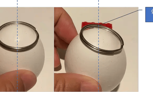
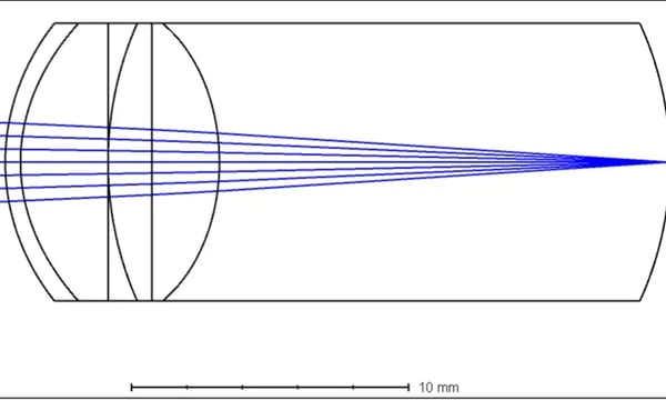
这几天想起来一个自拍眼底照相的论文,比较早了,是2015年MIT的一篇eyeSelfie: Self Directed Eye Alignment using Reciprocal Eye Box Imaging,这篇文章很有趣,他们设计了一种用户自己手动对焦的方式,制作了一个便携的眼底相机。但这个项目后续没有商业化,8年过去了也没有看到市售的产品,找到一家公司的网站https://www.identifeye.health/ ,似乎是在做类似这个自拍眼底相机(血管扫描?)的产品,但该公司最后一次更新新闻是在2021年7月,后来就再无声息,估计是黄了。
不过,这篇文献仍然很有趣,特别是他们设计眼底相机的过程,用的是ABCD矩阵,看起来就是一个眼底相机设计教程。所以我打算仔细研读,干脆先把其中关于设计的部分先翻译了。
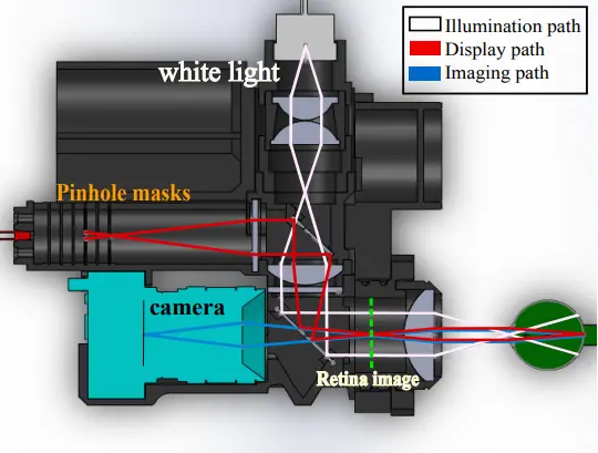
译文如下:
3. System Overview
We start with the theoretical framework to design a display which ensures accurate self-alignment of the pupil and proper illumination of the retina in our imaging system. HMDs are divided into two distinct classes: pupil forming and non-pupil forming displays [Kress and Starner 2013]. In pupil forming designs, the eyepiece’s eye box is determined by the system’s exit pupil. These designs relay an image onto the retina through the observer’s pupil. The optical design for retinal imaging systems can be thought of as the inverse, in which the image of the retina is relayed through the pupil and onto an image sensor. We develop our retinal imaging theory by inverting the ray model for pupil-forming head mounted displays using the thin lens approximation [Dodgson 2002; Lanman and Luebke 2013]. In short, we want to construct an eye box in the display path that matches the eye box of the illumination path.
3. 系统概述
我们从理论框架开始,设计一个能确保瞳孔的准确对齐以及我们成像系统中视网膜的适当照明的展示。头戴式显示设备 (HMDs) 分为两个明显的类别:瞳孔形成和非瞳孔形成的显示器 [Kress 和 Starner 2013]。在瞳孔形成的设计中,观察镜的eye box由系统的出瞳确定。这些设计通过观察者的瞳孔将图像输送到视网膜。视网膜成像系统的光学设计可以被视作一个逆过程,在这个过程中,通过瞳孔将视网膜的图像传递到一个图像传感器上。我们利用薄透镜近似理论 [Dodgson 2002; Lanman 和 Luebke 2013],将用于头戴式显示器的瞳孔形成的射线模型反转,从而发展我们的视网膜成像理论。简单来说,我们希望在显示路径中构建一个与照明路径的eye box相匹配的eye box。
3.1 Imaging System
The retina absorbs a large amount of light but is only visible through a small aperture, the pupil. The region in front of the pupil, the cornea, produces strong specular reflections due to the index of refraction mismatch of ambient air and hydrated tissue. This situation motivates us to develop a cohesive illumination strategy to image the retina.
3.1 成像系统
虽然视网膜能够吸收大量光线,但其观察视野却只限于一个小孔——瞳孔。而位于瞳孔前方的角膜,由于其与环境空气和水合组织的折射率不匹配,会产生强烈的镜面反射。为了克服这个问题,我们开发出了一种全面的照明策略来对视网膜进行成像。
It is useful to model our system using geometrical optics and the thin lens approximation. At a plane along the optical axis, we parameterize the set of rays with two dimensions of space (x, y) and two dimensions of direction (u, v), where u = tan(θ) and v = tan(φ) are the conversions of the rays from spherical coordinates. The light field at the retinal plane l(x, y, u, v) relates to the illumination path and imaging system by a coordinate transformation.
我们采用几何光学和薄透镜近似模型来建立我们的系统模型。在光轴的一个平面上,我们用两个空间维度(x,y)和两个方向维度(u,v)来参数化光线,其中u = tan(θ)和v = tan(φ)是光线由球面坐标转换过来的参数。视网膜平面上的光场l(x, y, u, v)与照明路径和成像系统之间存在一个坐标变换关系。
To simplify our analysis, we will use one spacial dimension along and consider the 2D light field (Figure 3), l(x, u), moving through our system. This leads to a simple set of operations which we can perform using basic optical components. First, the light field at some distance, d, along the optical axis can be described by the free space propagation operator:
\[S_d=\begin{bmatrix}1&d\\0&1\end{bmatrix} \tag1 \]
为了简化分析,我们将光场沿着一个空间维度分析,并考虑2D光场(如图3),即l(x, u),通过我们的系统进行传输。这导致了一组简单的操作,我们可以使用基本光学元件来执行。首先,光场在光轴上某一距离d处的表现可以用自由空间传播算子来描述:
\[S_d=\begin{bmatrix}1&d\\0&1\end{bmatrix} \tag1 \]
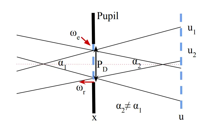
Figure 3: Geometry of Rays at Pupil. We define a set of rays using the two plane parameterization of the light field at the pupil. The eye can move a certain distance laterally (ωe), or axially (ωr) relative to the imaging system. The x-plane at the pupil describes the location of rays in space, and the u-plane describes the direction the rays are headed. We observe the two virtual pinholes at the pupil plane where the generated rays intersect. The user’s pupil integrates both of the images generated by these two pinholes when properly aligned.
图3:瞳孔处的光线几何。我们使用瞳孔处的光场的两平面参数化来定义一组光线。眼睛可以相对于成像系统在横向(ωe)或轴向(ωr)移动一定距离。位于瞳孔的x-平面描述了光线在空间中的位置,而u-平面则描述了光线的行进方向。我们观察到在瞳孔平面处生成的光线交叉的两个虚拟针孔。当正确对准时,用户的瞳孔将整合由这两个针孔生成的图像。
This matrix describes a shear in the 2D light field in 1D space, where rays in free space do not change direction and continue the direction they were headed. We can next describe the spherical thin lens operator. This describes another shear operation in u:
\[L_f=\begin{bmatrix}1&0\\-1/f&1 \end{bmatrix} \tag2 \]
这个矩阵描述了在一维空间内的二维光场的切面操作,其中光线在自由空间中的方向并未发生改变,而是继续朝着原来的方向前进。接下来,我们可以描述球面薄透镜算子。这个算子描述了在u方向上的另一种切面操作:
\[L_f=\begin{bmatrix}1&0\\-1/f&1 \end{bmatrix} \tag2 \]
Finally, we notice that an aperture that blocks rays in an area in space, Ω, extinguishes rays over the entire u dimension. We describe this using the pupil operato, P
\[P_{\Omega}(l)\to l(x_{\Omega},u)=0 \tag3 \]
最后,我们要注意,一个在空间中阻挡光线的光阑,Ω,会将整个u维度上的光线都熄灭。我们用瞳孔算子P来描述这一现象。
\[P_{\Omega}(l)\to l(x_{\Omega},u)=0 \tag3 \]
We can then use this notation to describe light entering the eye and illuminating the retina. The light field at the cornea, lc, is refracted by the cornea, stopped by the pupil, further refracted by the lens, and travels to the retina. We recover the observed irradiance on the retina by summing over all the incident angles at each point in space.
\[I_r(x)=\sum_u S_e L_e P_\Omega (S_cL_cl_c) \tag4 \]
接着,我们可以利用这些符号来描述光线如何进入眼睛并照亮视网膜。角膜上的光场lc经过角膜的折射和瞳孔的阻挡,再通过透镜的进一步折射,最终到达视网膜。我们通过对空间中每个点的所有入射角度进行求和,来得到我们观察到的视网膜上的辐照度。
\[I_r(x)=\sum_u S_e L_e P_\Omega (S_cL_cl_c) \tag4 \]
We can use this model to understand how light is transformed by the eye in order to construct a system to image it.
我们可以利用这个模型来理解光线在眼睛中的变换情况,以便构建一个成像系统。
Corneal Reflections
The reflections of the illumination engine back into the imaging system can produce undesirable out of focus reflections, reducing the noise floor of acquired images. We model corneal reflections as the image produced by a convex spherical mirror with a radius of curvature of R=7.2mm. We calculate the rays which will reflect back into our imaging system using Equations 1 and 2. The 2D light field after reflecting off the cornea and reaching the objective lens is:
\[\begin{bmatrix}x^{\prime}\\u^{\prime}\end{bmatrix}=\begin{bmatrix}x(1-\frac{f_L}{f_c})+f_Lu\\-\frac x{f_c}+u\end{bmatrix}\tag5 \]
角膜反射
照明引擎反射回成像系统会产生不良的焦外反射,降低了所采集图像的噪声底限。我们将角膜反射建模为一个半径为R=7.2mm的凸面球镜产生的图像。
我们利用等式1和2来计算哪些光线会反射回我们的成像系统。反射自角膜并达到目标透镜后的2D光场是:
\[\begin{bmatrix}x^{\prime}\\u^{\prime}\end{bmatrix}=\begin{bmatrix}x(1-\frac{f_L}{f_c})+f_Lu\\-\frac x{f_c}+u\end{bmatrix}\tag5 \]
where fL is the focal length of the objective lens and fc is the effective focal length of the reflective cornea, defined by fc = −R/2. We then establish the light field at the image plane behind the objective.
\[\begin{bmatrix}x^{\prime\prime}\\u^{\prime\prime}\end{bmatrix}=\begin{bmatrix}f_L(-\frac x{f_c}+u)\\x(\frac1{f_c}-\frac2{f_L})+u(1+f_L)\end{bmatrix} \tag6 \]
其中fL是目标透镜的焦距,fc是反射性角膜的有效焦距,fc的定义为fc = −R/2。接着我们确定目标透镜后方图像平面上的光场。
\[\begin{bmatrix}x^{\prime\prime}\\u^{\prime\prime}\end{bmatrix}=\begin{bmatrix}f_L(-\frac x{f_c}+u)\\x(\frac1{f_c}-\frac2{f_L})+u(1+f_L)\end{bmatrix} \tag6 \]
We note that in order for the rays to stay in the system, \(|x^\prime| \lt D/2\), where D is the diameter of the objective lens. Similarly, \(|x^{\prime\prime}|\) must be within the FOV of the camera. We can thus write the bound on u in the light field as a function of x using Equations 5 and 6 to solve the inequality imposed by the objective lens and camera apertures.
\[-\frac D{2f_L}+\frac x{f_c} \lt u \lt \frac D{2f_L}+\frac x{f_c} \tag7 \]
\[-\frac D{2f_L}-x\left(\frac1{f_L}-\frac1{f_c}\right) \lt u \lt \frac D{2f_L}-x\left(\frac1{f_L}-\frac1{f_c}\right) \tag8 \]
我们注意到为了保持光线在系统内,\(|x^\prime| \lt D/2\),其中D是目标透镜的直径。类似地,\(|x^{\prime\prime}|\)必须在相机的FOV内。因此,我们可以使用等式5和6将光场中u的界作为x的函数来写出,以解决目标透镜和相机孔径强加的不等式。
\[-\frac D{2f_L}+\frac x{f_c} \lt u \lt \frac D{2f_L}+\frac x{f_c} \tag7 \]
\[-\frac D{2f_L}-x\left(\frac1{f_L}-\frac1{f_c}\right) \lt u \lt \frac D{2f_L}-x\left(\frac1{f_L}-\frac1{f_c}\right) \tag8 \]
We take the intersection of these two regions to determine the area of the light field at the cornea, which will reflect back into the system.
We observe that converging rays towards the center of the imaging axis (x and u opposite signs and small) account for most reflections back into the system. This analysis explains the motivation for the annular type illumination popular in mydriatic fundus cameras. Non-mydriatic systems such as ours must still deliver much of the light through a smaller pupil, therefore cross polarized illumination is used to reduce reflections at the image plane. Furthermore, this analysis suggests that the eye should be further than the focus of converging illumination to avoid localized reflections, which we confirm with experimental observation in Section 4.3 (see Figure 5)
我们取这两个区域的交集,以确定在角膜上的光场的区域,这将反射回系统。
我们发现汇聚向成像轴中心的光线(x和u有相反的符号且小)占系统反射的大部分。该分析解释了瞳孔扩大眼底照相机中流行的环状照明的动机。非扩瞳系统,如我们的,仍然需要通过更小的瞳孔传递很多光,因此采用交叉偏振光来降低图像平面上的反射。此外,该分析还表明眼睛应远离汇聚照明的焦点,以避免局部反射,我们在4.3节通过实验证实了这一点(参见图5)。
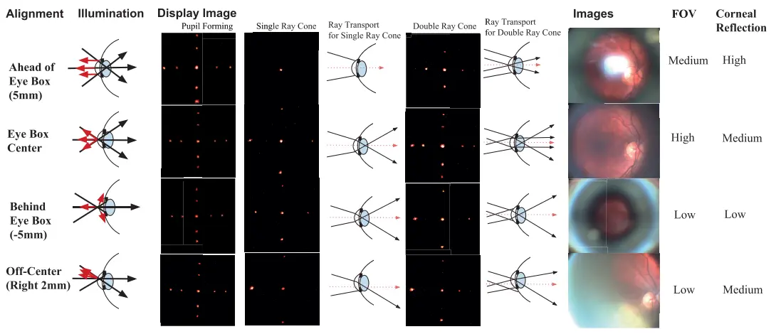
Figure 5: Physical Alignment and Perceived Display. Starting from the left. Alignment: There are four primary locations the eye can be relative to the eye box center; well aligned, too close and too far from the instrument, and off center. Illumination: A collimated illumination source is focused by the objective lens to a point near the eye pupil, reflected light behaves differently depending on the location of the eye relative to the illumination focus. Display Image: Three alignment strategies are used to match the display to the illumination eye box. Each position produces a distinct type of retinal image for the two ray cone pattern. Images: Reflections from the cornea appear as localized bright spots due to the cornea re-collimating reflected rays. The pupil blocks marginal rays that are too far or off center. FOV and Corneal Reflection: The FOV and reflection pattern are highly specific to the eye location relative to the instrument.
图5:物理对齐和感知显示。从左边开始。对齐:眼睛可以相对于眼睛盒子中心的四个主要位置;良好的对齐,离设备过近和过远,以及偏离中心。照明:由目标透镜聚焦的平行照明源,聚焦点位于眼睛瞳孔附近,反射光根据眼睛相对于照明焦点的位置的不同而表现出不同的行为。显示图像:使用三种对齐策略将显示器匹配到照明眼盒。每个位置都会对两个射线锥形图案产生一种明显的视网膜图像。图像:由于角膜对反射的射线进行再汇聚,角膜的反射看起来像是局部的亮点。瞳孔阻挡了离得过远或偏离中心的边缘射线。视场和角膜反射:视场和反射模式与眼睛相对于设备的位置高度相关。
Retinal Illumination
The pupil restricts the spatial extent of incident light that makes it to the retina. The pupil diameter contracts with increased ambient light. The relaxed pupil size varies from person to person. Quality retinal images require even illumination across the fundus. It is this series of factors which suggest a converging beam focused onto the pupil as the best illumination strategy. This is called Maxwellian illumination, where the fullcone angle is denoted as α. One large drawback to Maxwellian illumination is a greatly reduced eye box. We solve this problem by introducing an alignment dependent display and by establishing a stimulus to direct the user into the illumination eye box as accurately as possible.
视网膜照明
瞳孔限制了射入光线到达视网膜的空间范围。随着环境光线的增加,瞳孔直径会缩小。放松状态下的瞳孔大小因人而异。获取高质量的视网膜图像需要在眼底实现均匀照明。正是这系列因素暗示了将汇聚光束聚焦到瞳孔可能是最佳的照明策略。这种策略被称为Maxwellian照明,其中,全锥角被记为α。但Maxwellian照明的一个大缺点是eye box显著缩小。我们通过引入一个依赖于对准的显示器,并设立一种刺激,以尽可能精确地引导用户进入照明eye box,从而解决了这个问题。
Pupil Alignment
Correct positioning of the eye in space is absolutely critical and needs to address six degrees of freedom: three translational, two rotational, and one focal. The approach to achieve eye alignment could be creating an image that is only visible to the user when they are in the illumination eye box. Our approach is to create a display which matches our illumination eye box. Moreover, the display eye box should be restricted to ensure that the user does not move closer than the illumination focus, which would cause unwanted corneal reflections.
瞳孔校准
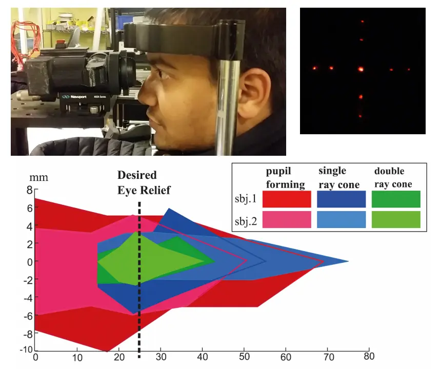
Figure 4: Measuring Eye Alignment. Top: The subject was asked to report when the perceived image (top right) was disrupted after moving the device on the translation stage. Bottom: The actual eye box was measured using three different display methodologies for lateral (vertical axis) and axial (horizontal axis) translation of the observing eye relative to the imaging system. The system was moved relative to the subjects stationary head position. Each subject started 100mm from the imaging system and was asked to report when they could view the display and when it disappeared upon moving too close. The subjects were then asked to report the lateral offset in which occlusion of the display occurred for five evenly spaced axial distances from these two extreme points. The dotted line is the desired eye relief, the distance from the imaging system which would allow the marginal rays of the illumination to maximally clear the pupil.
图4:测量眼睛对齐情况。上图:被测试者被要求报告,当移动设备时,在平移舞台上感知到图像(右上图)出现故障的情况。下图:我们使用三种不同的显示方法测量了实际眼盒,这涉及到相对于成像系统观察眼睛的横向(垂直轴)和轴向(水平轴)的转移。系统相对于被试的头部固定位置进行移动。每位被试都从离成像系统100mm的地方开始,然后被要求报告他们何时可以观察到显示器,以及当移动过近时显示器何时消失。接着,被试被要求在这两个极值点之间的五个等间距的轴向距离上报告显示器开始遮挡的横向偏移情况。虚线表示所需的视眼间距,这是离成像系统的距离,能让照明的边缘光线最大程度地清晰通过瞳孔。
在空间中精确地定位眼睛极其重要,这涉及到解决六个自由度的问题:三个是平移自由度,两个是旋转自由度,还有一个是焦距自由度。一种可能的眼睛校准方法是制作一种只有当用户位于照明eye box内时才能看到的图像。我们采用的方法是制作一款与我们的照明eye box相匹配的显示器。此外,还需要对显示器的eye box进行限制,以防止用户过于靠近照明焦点,从而产生不必要的角膜反射。
Pupil forming displays have the ability to control the relative rotation given a fixed location in space. They address rotational and focal degrees of freedom of the eye with a limited ability of the viewer to know where their eye is located in space. In order to address spatial degrees of freedom for alignment, we use a ray-based approach, which we call a single ray cone design. These kinds of displays create a ray of cones along the marginal rays of a focused beam, such as our Maxwellian illumination source. This method is highly effective for constraining lateral movement (x, y), but it does not fully address the problem of alignment in depth (z). To address this final degree of freedom, we introduce another set of converging rays, which when combined with a single ray cone becomes a double ray cone.
瞳孔形成显示器具有控制相对旋转的能力,给定一个固定的空间位置。他们解决了眼睛的旋转和焦距自由度问题,但观查者对其眼睛在空间中位置的了解能力有限。为了解决对齐的空间自由度,我们采用一种基于光线的方法,我们称之为 单光线锥设计。此类显示器会沿着聚焦光束的边缘射线创建一束光锥,例如我们的马克斯韦尔照明源。这种方法对于限制横向移动(x,y)非常有效,但是它并没有完全解决在深度(z)方向上的对齐问题。为了解决这个最后的自由度问题,我们引入了另一组汇聚的光线,当它们与单光线锥结合时,就形成了一个双光线锥。
The marginal rays that describe the ray cone have an angle of extent, denoted by α. The eye box for this illumination source, known as ωe, can be determined as a function of z.
\[\omega_e(z)=P_D-2\left|z-z_0\right|u_\alpha \tag9 \]
描述光线锥的边缘光线有一个角度范围,记作 α。这种照明源的眼盒,被称为 ωe,可以作为 z 的函数来确定。
\[\omega_e(z)=P_D-2\left|z-z_0\right|u_\alpha \tag9 \]
where for an extended angle, α, adopting the notion that u = tan(α/2), and that \(P_D\) is the diameter of the subject’s pupil, we then can determine the maximum axial distance of the eye, denoted as zr, from the ray intersection at z0 by solving for when ωe = 0, or
\[z_r=\frac{P_D}{2u_\alpha} \tag10 \]
对于扩展的角度α,我们采用的概念是 u = tan(α/2),并且 \(P_D\) 是受试者的瞳孔直径。然后,我们可以通过求解 ωe = 0来确定眼睛的最大轴向距离,记作zr,该距离是从射线交点在z0 开始的,公式如下:
\[z_r=\frac{P_D}{2u_α} \tag10 \]
We observe that in order to achieve a full FOV, the marginal rays of the illumination beam must pass the pupil. The marginal rays must be distinct from the rest of the rays entering the pupil to indicate to the user that they have made it through. The simplest solution is to produce only the marginal rays of the illumination. If the user sees them, then we can assume the system is well aligned. Ideally, we want to further constrict the eye box of the display so that we avoid situations where the marginal rays may scatter off the edge of the pupil. To this end, we want to pick a set of rays which produces an eye box that is smaller than the illumination eye box, ωe. The set of rays is shown in Figure 3. We also note that when the eye is focused to infinity, u must be unique for each ray in order to avoid a mbiguity, since an eye focused to infinity will map each ray with the same u to the same location on the retina. Our set of rays is:
\[\left.l_c=\left(\begin{array}{cccc}\frac{P_D}2&\frac{P_D}2&-\frac{P_D}2&-\frac{P_D}2\\-u_1&u_2&u_1&-u_2\end{array}\right.\right)\tag{11} \]
我们观察到,为了实现全视场(FOV),照明光束的边缘射线必须通过瞳孔。边缘射线必须与进入瞳孔的其余射线不同,以向用户表明他们已经通过。最简单的解决方案是只产生照明的边缘射线。如果用户看到它们,那么我们可以认为系统对齐得很好。理想情况下,我们希望进一步缩小显示器的眼孔,以避免边缘射线可能在瞳孔边缘散射的情况。为此,我们希望选取一组在产生眼孔尺寸方面比照明眼孔,ωe,更小的射线。这组射线显示在图3中。我们也注意到,当眼睛聚焦到无限远时,为了避免歧义,u 必须对每条射线都是唯一的,因为聚焦到无限远的眼睛会把每条具有相同u的射线映射到视网膜上的同一位置。我们选择的射线组为:
\[\left.l_c=\left(\begin{array}{cccc}\frac{P_D}2&\frac{P_D}2&-\frac{P_D}2&-\frac{P_D}2\\-u_1&u_2&u_1&-u_2\end{array}\right.\right)\tag{11} \]
Where PD is the user’s pupil diameter and (u1, u2) are two sufficiently distinct ray angles that make it through the imaging system.
其中,PD 是用户的瞳孔直径,(u1, u2) 是两个足够不同的射线角,它们可以通过成像系统。
The set of rays defined by equation 11 is shown in Figure 3, representing a double ray cone pattern with ray intersections at different distances from the eyepiece. As such, to define the eye box of this design, we simply take the intersection of equation 9 applied to u1 and u2.
如图3 所示,由公式11 定义的一组射线代表了一个具有在距离目镜不同距离处的射线交点的双射线锥模式。因此,要定义这个设计的眼盒,我们只需要取公式9 应用于 u1 和 u2 的交集。
We now describe our display optics using a combination of equations 1 and 2 for each optical element, which produces a 2 × 2 ray transfer matrix T for the 2D light field case.
\[T=S_1L_1S_2L_2...S_nL_n \tag{12} \]
现在,我们将对于每一个光学元素使用公式1 和公式2 的组合来描述我们的显示光学,这为2D 光场情况产生了一个 2 × 2 的光线传输矩阵 T。
\[T=S_1L_1S_2L_2...S_nL_n \tag{12} \]
The light field at the display, \(l_d\), propagates through our optical system, and produces a light field at the eye pupil \(l_c = T l_d\). We can then solve this equation for the desired light field at our display, ensuring that the resulting light field clears the system’s exit pupil \(P_E\).
显示器的光场 \(l_d\) 通过我们的光学系统传播,并在眼瞳生成一个光场 \(l_c = T l_d\)。我们接下来就可以解此公式,求出我们在显示器上想要的光场,确保最后得到的光场可以清楚地经过系统的出瞳 \(P_E\)。
\[l_d=T^{-1}l_c \tag{13} \]
We observe that the double cone approach addresses all the degrees of freedom in eye alignment. We use this approach to generate our desired light field at the pupil. Figure 3 illustrates this light field and Figure 5 shows the ray transport for the four distinct eye alignment scenarios. This ray pattern could be interpreted as five virtual pinholes at the eye’s pupil plane, allowing for spacial coding of the perceived image as the user’s pupil samples different combinations of these virtual pinholes. We construct the light field in our display using two masks 12mm apart, where the mask closest to the magnifier lens is one focal length away in order to provide a focus cue for the user. Our analysis could be applied to other light field displays such as those formed by lenslet arrays, but we elected to use a pair of pinhole masks to allow for finer angular control of the generated light field.
\[l_d=T^{-1}l_c \tag{13} \]
我们观察到,双射线锥体方法解决了眼睛对准的所有自由度问题。我们使用这种方法在瞳孔处产生我们想要的光场。图3 描绘了此光场,图5 显示了四种不同眼睛对准情况的射线传递。这种光线模式可以被解读为在眼瞳平面上的五个虚拟针孔,允许用户的瞳孔以不同的针孔组合样本对感知图像进行空间编码。我们使用两个相距12mm 的遮罩在显示器上构造光场,最靠近放大镜片的遮罩离其一焦距远,用以提供用户的焦点提示。我们的分析可以用于其他光字段显示,如透镜阵列形成的显示,但是我们选择使用一对针孔遮罩以实现对生成光场更精细的角度控制。
对比一下eyeSelfie的设计

和蔡司眼底相机的设计
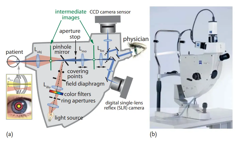
照明光路上比较相似,关键是要将照明光束的焦点放在瞳孔中央。成像光路上,蔡司的眼底相机更复杂一些,多了一步成像,是为了加小孔限制杂散光。
