
In this group photograph, the real subject is the room.
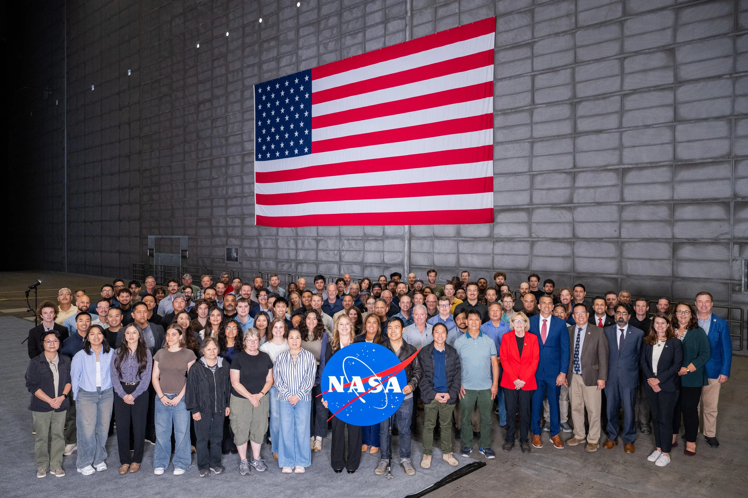
Image: NASA Image of the Day · Image credit: Brandon Torres Navarrete · Image page
This is a group photograph.
NASA's caption is matter-of-fact: "New civil servants and guests pose for a group photo with NASA and center leadership in the National Full-Scale Aerodynamics Complex (NFAC) 80-foot by 120-foot test section (N221), Monday, Aug. 24, 2026. The civil servants were sworn in earlier that day during the largest swearing-in ceremony in the nearly 87-year history of NASA's Ames Research Center in California's Silicon Valley."
An induction ceremony would not normally need an entire article.
But look at the place where they are standing.
The people are as small as a row of pins. Behind them, rectangular walls rise and rise until the passage is cropped by the top of the frame. This is not a hall or a hangar. It is the inside of a machine.
They are standing inside the world's largest wind tunnel.
The room has to be this big because of a hard fact of physics: you cannot cheat with a small model. That is the story here.
First, Define "Largest"
Official sources use different superlatives for this facility. The distinctions are revealing.
The fact sheet from its operator, the US Air Force's Arnold Engineering Development Complex, is the most direct: "The 80-foot by 120-foot test section is the world's largest wind tunnel, capable of testing a full-scale Boeing 737 at speeds up to 100 knots."
NASA Ames Research Center adds a qualifier on its own page: the world's largest subsonic wind tunnel, more than 1,400 feet long and 180 feet high.
A NASA historic-building document, written about N-221, the 40-by-80-foot tunnel, uses a third phrase: the world's largest low-speed wind tunnel.
Which is right? All three, because the qualifier is the story. The facility is largest by cross-sectional area, not by speed or power. That is why China's JF-22 can simultaneously be world-leading. The two facilities lead along different axes. This article uses "world's largest subsonic wind tunnel," the wording on NASA's own website.
There is another surprise: the tunnel is now operated by the US Air Force. Its fact sheet says that the National Full-Scale Aerodynamics Complex at NASA Ames, Moffett Field, California, is operated by the Air Force's Arnold Engineering Development Complex. The Air Force leased the facility from NASA in 2006, after it closed in 2003, and achieved full operational capability in early 2008. NASA's rotorcraft page confirms the arrangement, describing a long-term lease agreement with NASA.
A wind tunnel built by NASA was mothballed, then leased back into operation by the Air Force.
How Big Is the Machine?
The official dimensions and speeds of its two test sections are these:
The 40-foot by 80-foot section measures 12.19 by 24.38 meters. It is a closed, single-return tunnel with a maximum speed of 300 knots.
The 80-foot by 120-foot section, the one in the photograph, measures 24.38 by 36.58 meters. It is an open-return tunnel with a maximum speed of 100 knots.
Converting the units is useful because the Air Force and NASA report them differently, making identical figures look contradictory. Three hundred knots is 555.6 kilometers per hour, 154.3 meters per second, or 345 miles per hour, exactly the figure on NASA's page. One hundred knots is 185.2 kilometers per hour, 51.4 meters per second, or 115 miles per hour, again matching NASA. The Air Force reports knots and NASA miles; the numbers are the same.
One genuine discrepancy remains unresolved. NASA's 1993 calibration report says the 80-by-120-foot test section is 120 feet long. NASA's current facility page says 190 feet long. Both are NASA sources. The difference may depend on where the boundary is drawn: around the bare test section alone, or including the acoustically treated transition. This article does not choose a single figure.
The drive system is what truly takes the breath away. The Air Force fact sheet says:
"The new fan drive system consists of six variable-pitch fans, each 40 feet in diameter, arranged in two rows of three fans each. Each fan consists of 15 laminated wood blades driven by a 22,500-horsepower electric motor."
"The six fans rotate together at 180 rpm, consume 106 megawatts of electricity at full power, and move more than 60 tons of air per second."
Six times 22,500 is 135,000 horsepower, equivalent to 100.7 megawatts, the "101 megawatts" on NASA's page.
So is the Air Force's 106 megawatts wrong, or NASA's 101? Neither. The first is electrical consumption and the second shaft power. Divide one by the other and the result is 95.0 percent, a plausible efficiency for large industrial motors. The missing 5 megawatts becomes heat instead of wind. This is not an official contradiction. It is a lesson.
One more number follows directly from the specifications. A 40-foot diameter is 12.19 meters and a circumference of 38.3 meters. At 180 revolutions per minute, the fan turns three times per second.
The blade tips travel at 114.9 meters per second, or 414 kilometers per hour.
Their tips must run at 414 kilometers per hour to push the air to 185 kilometers per hour.
And those 12-meter blades are made of laminated wood. That is the Air Force's own term.
Every Second, the Room Gets All New Air
This is the finest calculation in the source material because it falls straight out of the official figures.
The acoustically lined cross section measures 78.5 by 118 feet, or 23.93 by 35.97 meters = 860.6 square meters. Multiply it by the maximum speed of 51.4 meters per second:
About 44,300 cubic meters of air per second.
At sea-level air density, 1.225 kilograms per cubic meter, that is 54.2 metric tonnes per second, or 59.8 US short tons.
The Air Force says "more than 60 tons per second." Its own dimensions and speed produce 59.8. The numbers check themselves.
Then comes the most striking inference. Using a length of 120 feet, the test section's volume is 31,476 cubic meters. Using 190 feet, it is 49,837 cubic meters. Divide either by 44,300 cubic meters per second:
0.71 seconds, or 1.13 seconds.
Whichever length is used, every trace of air in this cathedral-sized room is thrown out and replaced roughly once a second.
This is the article's calculation from parameters published by NASA and the Air Force, not an official quoted figure.
NASA Said the Essential Thing in Fourteen Words
Now for why the machine works.
NASA Glenn Research Center's Beginner's Guide to Aeronautics contains the sentence on which this entire story turns:
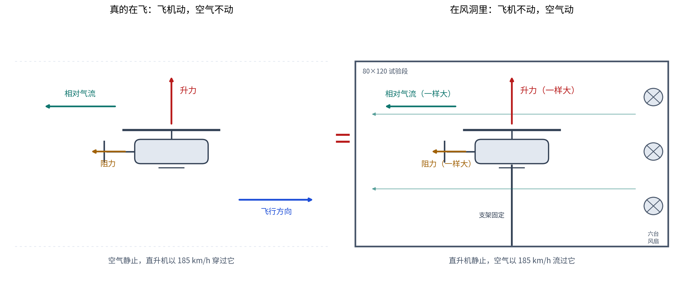
"The forces are the same if the object moves through the air, or the air moves over the object."
The same page applies the idea to a wind tunnel: ground speed is zero because the model is fixed to the tunnel walls; airspeed is the negative of the wind speed generated in the tunnel.
NASA Ames puts it more plainly: a wind tunnel works by moving air past a stationary object, making the object seem to fly.
Fourteen words settle the matter. The principle is Galilean relativity: motion is relative. From inside the system, you cannot distinguish "I am moving" from "everything around me is moving."
Keep the airplane still and move the air. The forces are identical.
Engineers do not need to fly the airplane. They can tie it down and send air across it at 185 kilometers per hour. The airplane behaves as though it were flying. It produces real lift, real drag and real vibration while engineers stand nearby and watch with instruments.
Why Not Use a Small Model?
A natural question follows. If only the airflow matters, why build a cathedral? Would it not be cheaper to make a one-tenth-scale airplane and blow air over it in a small room?
Because physics does not allow it. That is the reason this building exists.
NASA Glenn's wind-tunnel guide states the requirement clearly:
"Aerodynamicists use wind tunnels to test models of proposed aircraft. In a wind tunnel, engineers can carefully control the flow conditions which affect forces on the aircraft." By carefully measuring forces on a model, engineers can predict forces on the full-scale aircraft. But they must ensure that the Mach number and Reynolds number, two flow-similarity parameters, match the intended flight conditions.
The key is the Reynolds number. NASA defines it as the ratio of inertial forces to viscous forces. Its plain-language glosses are even better: inertia resists a change in motion; viscosity is what makes a fluid thick and sticky.
The formula is Re = rho VL/mu: density multiplied by speed and characteristic length, divided by viscosity.
Shrink the model, and L becomes one tenth as large. To keep the Reynolds number unchanged, the air must move ten times faster.
At ten times the speed, the flow breaks the sound barrier and destroys the other required similarity, the Mach number. Fix one condition and the other fails.
Other solutions exist. Engineers can increase density, rho, which is why Ames also has a 12-foot pressure wind tunnel. Or they can reduce viscosity, mu, in a cryogenic tunnel. Both are real techniques with costs of their own.
Or do not shrink anything. Let L be the length of a real airplane and build the room around it.
That is NFAC.
NASA's historical timeline says it most directly in the language of 1944:
"1944 - The Ames 40-by-80-foot full-scale wind tunnel becomes operational. It allowed entire aircraft to be placed in the wind tunnel for testing, rather than models as had previously been done at low flight speeds, and expanded testing capability to larger and faster aircraft."
The room is this large because physics will not let a small model cheat.
One qualification is necessary. NASA states the requirement to match Reynolds number, but no single NASA page explicitly works through the small-model dilemma above. That reasoning is derived here from NASA's published formula; it is not a NASA quotation.
It Does Not Just Watch. It Weighs
How does a wind tunnel turn "force" into a number?
The two NFAC test sections share equipment called the Large Rotor Test Apparatus. NASA describes it as a specialized drive and support system capable of operating helicopter rotors at up to 52,000 pounds of thrust.
That is 23.6 metric tonnes of thrust. NASA lists three instruments mounted on the apparatus:
A five-component rotor balance measures steady and unsteady rotor-hub loads. A torquemeter flex coupling measures rotor torque. A six-component fuselage load-cell system measures steady fuselage loads.
Its limits include 15,000 pounds of resultant shear, 125,000 foot-pounds of resultant bending moment, 165,000 foot-pounds of torque and 320 revolutions per minute.
The machine does more than watch an aircraft in the wind. It straps the aircraft to a scale and reports six numbers at once, including unsteady, instantaneous changes in load.
A Full-Scale Helicopter Rotor Became Visible Indoors
Now for a concrete case.
Early in 1992, a full-scale Sikorsky S-76 rotor was installed in the 80-by-120-foot section.
NASA's rotorcraft research page records the test. Wind speed was swept from zero to 100 knots through different shaft angles and thrust states while researchers measured pressure on the tunnel walls, ceiling and floor. They also used shadowgraph imaging to photograph the rotor wake, capturing the roll-up of tip vortices, the inboard wake vorticity and the unsteadiness of the flow at advance ratios as high as 0.25.
A full-size helicopter rotor stirred the air, and the shape of that air was photographed indoors in 1992.
The experiment found something practically important as well. Pressure distributions on the tunnel walls were affected by the presence of the rotor, especially at low speeds. A room can be enormous and still not disappear from the experiment. They measured that too.
The facility's service record is long. Air Force material names the A-26 Invader, F-84, F-86, Kaman K-16B, V-22 Osprey, S-76, AV-8B Harrier, F-14 Tomcat, a scale space-shuttle model and the Apollo parachute recovery system. Another Air Force article mentions the F-35, P-8, F-18 and UH-60 Black Hawk, as well as tests of rotor and tiltrotor rigs at speeds never before reached anywhere on Earth.
The official list of applications also includes several things that do not immediately sound aeronautical: wind turbines, parachutes, trucks and other nontraditional tests.
Trucks have been blown through the world's largest wind tunnel.
The Room's Limits Teach More Than Its Size
There is one thing this wind tunnel cannot test, and the reason is worth understanding.
It cannot test a Mars parachute.
A supersonic parachute for Mars must be tested at supersonic speed. This tunnel tops out at 100 knots, or 185 kilometers per hour. No one can build a room large enough to contain the test at supersonic speed.
What did NASA do? It fired the parachute into the sky. On October 4, 2017, the Mars 2020 parachute-testing project launched a 58-foot, or 17.7-meter, Black Brant IX sounding rocket from Wallops Flight Facility and deployed the parachute at 42 kilometers altitude and Mach 1.8.
To test a parachute for Mars, you must shoot it into the upper atmosphere.
NFAC does test parachutes. Apollo's recovery parachutes were tested here. But those were subsonic parachutes.
The room has a limit, and the limit is itself a lesson. Some problems can be solved by enlarging the room. Others require leaving it.
Incidentally, When Was Ames Founded?
The image caption says "nearly 87 years." Subtract 87 from 2026 and the result is 1939.
NASA itself offers three official dates for the founding of Ames:
August 9, 1939: Congress authorized construction of a second National Advisory Committee for Aeronautics laboratory.
December 20, 1939: one page says "Ames was founded Dec. 20, 1939," and a NASA image-library caption says Russell Robinson, at right, supervised the first excavation for Ames Laboratory that day.
April 18, 1940: another source says Ames Aeronautical Laboratory, later NASA Ames Research Center, was established at Moffett Field, California, on that date.
Congressional approval came on one day, the first shovel entered the ground on another, and the laboratory was formally established on a third. All three dates appear on nasa.gov.
By saying "nearly 87 years," the photograph's caption effectively votes for 1939.
The honest answer is that a large institution comes into being slowly, not all at once on a single morning.
For scale, the full tunnel circuit is more than 1,400 feet long and 180 feet high, or 427 meters long and 55 meters high. The designation N221 in the caption belongs to the 40-by-80-foot building. NASA's historic-building document identifies it as the Ames Aeronautical Laboratory 40-by-80-foot wind tunnel. Its east-west facade is about 265 meters long, its south facade about 53 meters high, and its five floors contain 139,117 square feet.
The 80-by-120-foot tunnel built in 1982 is a connected but separate facility sharing the same drive system.
In other words, the two wind tunnels use the same six fans. They cannot both run at full speed at once. Officially, their flow paths are interconnected and allow coordinated operation, subject to specific restrictions on simultaneous use.
A Useful Comparison on the Same Site
Ames has another facility, the Unitary Plan Wind Tunnel. Construction began in December 1951 and finished in 1956. It contains an 11-by-11-foot transonic section, a 9-by-7-foot supersonic section and an 8-by-7-foot supersonic section. The transonic section operates near or at the speed of sound; the supersonic sections reach about Mach 2.5. NASA says:
"The Unitary Plan Wind Tunnel has tested most aircraft and spacecraft developed in the United States."
Set it beside the room in the photograph:
The 11-by-11-foot section is barely large enough to park a car, but can reach 2.5 times the speed of sound.
The 80-by-120-foot section is as large as a cathedral, but reaches only 185 kilometers per hour.
Size and speed impose an unavoidable tradeoff. The reason to choose size is the Reynolds number.
The China Connection: The Other Extreme
China also has a room that leads the world, but it occupies the opposite end of the tradeoff.
The official instrument page of the Institute of Mechanics, Chinese Academy of Sciences, lists the specifications of the JF-22 hypervelocity wind tunnel:
Mach 9 to 25; flow speed 3 to 10 kilometers per second; total temperature 3,000 to 10,000 K; effective test time 1 to 40 milliseconds; simulated altitude 40 to 90 kilometers; total tunnel length 167 meters; nozzle exit diameter 2.5 meters; test-chamber diameter 4 meters; and model sizes of 2 to 8 meters. It is located at the Huairou campus.
The official description is one narrow sentence: the world's only detonation-driven hypervelocity, high-enthalpy shock tunnel.
JF-22 passed acceptance by the National Natural Science Foundation of China on May 30, 2023, after five years of construction from 2018 to 2023. The project leader was Jiang Zonglin. The official assessment says its combined indicators, including effective test time, total temperature, total pressure and nozzle-flow-field size, are internationally leading. Another official sentence links it to its predecessor: JF-22 and JF-12 together constitute the only ground-test platform covering the complete flight corridor of near-space vehicles.
Its predecessor, the JF-12 flight-duplication wind tunnel, operates at Mach 5 to 9, with flow speeds of 1.5 to 3 kilometers per second, total temperatures of 1,500 to 3,500 K, a test time of 120 to 130 milliseconds, and a total length of 265 meters. It was completed in 2012. In 2016, the project won second prize in China's State Technological Invention Awards under the title Shock-Tunnel Experimental Technology for Duplicating Hypersonic Flight Conditions. The inventors were Jiang Zonglin, Zhao Wei, Liu Yunfeng, Wang Chun, Li Jinping and Yu Hongru. Official award material from the Beijing Municipal Science and Technology Commission described the problem as an international challenge unsolved for 60 years, and the achievement as a shift from simulation to duplication.
Something else happened that same year, and it is more revealing than any claim about who leads.
In 2016, Jiang Zonglin received the American Institute of Aeronautics and Astronautics Ground Testing Award, the first Asian scientist to win it in the award's 40-year history.
An American aerospace society honored the person behind the Chinese tunnel. This was not a contest but recognition across two ends of the same craft.
Several restraints are necessary. Online claims that China is "far ahead of the United States" have been questioned by experts and are not used here. The Chinese Academy of Sciences makes two narrower, firmer claims: "the world's only detonation-driven" facility and combined performance that is "internationally leading." The official site of the China Aerodynamics Research and Development Center also lists the low-speed FL-12 tunnel, whose test section is 4 meters wide, 3 meters high and 8 meters long, with a maximum speed of 100 meters per second. It was completed in 1971. The site does not call it "Asia's largest," so this article does not either.
Now place the two facilities side by side:
NFAC's 80-by-120: a 24-by-37-meter test section, airflow at 51.4 meters per second, and runs that can continue for hours. Its world record is largest.
JF-22: a 2.5-meter nozzle, airflow at 3,000 to 10,000 meters per second, and an effective test time of 1 to 40 milliseconds. Its world record is only.
JF-22's flow is 58 to 195 times faster than the 80-by-120's. The 80-by-120's cross-sectional area of 860.6 square meters is 72 times the 12-square-meter cross section of FL-12.
Both rooms do the same thing: hold the vehicle still and move the air. One makes the room large enough for a real airplane, because Reynolds number will not let a small model cheat. The other compresses the experiment into thousandths of a second in exchange for airflow traveling ten kilometers every second.
Size, speed and time: choose two.
The physics imposes the same tradeoff at opposite ends of the Earth.
Finally
Return to the group photograph.
People arrive for their first day of work and are brought into a room for a picture. The room is 24 meters high and 37 meters wide. Six fans with wooden blades stand behind a wall. Each blade tip can travel at 414 kilometers per hour. At full power, the system consumes 106 megawatts and throws 54 tonnes of air out of the room every second, replacing it all.
Once a second, all the air in the room changes.
The reason this room exists is a judgment written down in 1944: some things cannot be tested only as models.
So the engineers did not shrink the airplane. They enlarged the building. More than 80 years later, a new group stood inside it for a photograph. They looked like pins, which showed exactly how large the room was, and how seriously that old judgment had been taken.
Sources: NASA Image of the Day for August 27, 2026; the US Air Force Arnold Engineering Development Complex NFAC fact sheet; official NASA Ames Research Center pages; NASA rotorcraft research pages on wind-tunnel facilities, the Large Rotor Test Apparatus and the S-76 test; NASA's historic-building document, N-221 Reuse Guidelines; Zell, Performance and Test-Section Flow Characteristics of the NFAC 80- by 120-Foot Wind Tunnel (NASA TM, 1993); Moon, Wind Tunnels of the National Full-Scale Aerodynamics Complex (NASA); NASA Glenn Research Center's Beginner's Guide to Aeronautics; NASA historical timelines; the history of NASA's Unitary Plan Wind Tunnel; the Jet Propulsion Laboratory on Mars 2020 parachute testing; NASA's educator guide Exploring Flight: Wind Tunnels; official Institute of Mechanics, Chinese Academy of Sciences, instrument pages for JF-22 and JF-12; the Institute of Mechanics announcement of JF-22's acceptance; the Beijing Municipal Science and Technology Commission's State Science and Technology Award notice; the Chinese Society of Theoretical and Applied Mechanics; and the official website of the China Aerodynamics Research and Development Center.